The railway joints are getting controlled over WIFI. I created a website on my Raspberry Pi and that’s working fine for quite a while. But I’m notereally satisfied switching the webbrowser and the BlueRail app on my mobile for controlling the loco and turing a joint. So I started to build a WIFI remote controller for the railway joints.
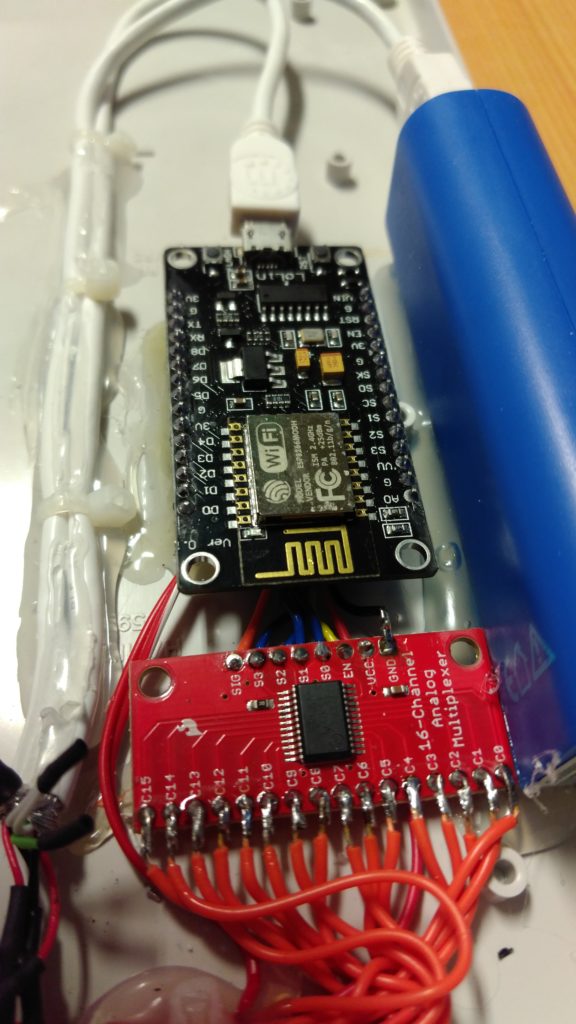
First problem is, that a ESP8266-12 on has about 10 working GPIO’s, which is sufficiant to control 5 railway joints. Not that much – that’s what I think. I had a CD74HC4067 16-channelmultiplexer breakout board left in my basement. So this requires a little more programming efforts, but it is expandable. So you only need 5 GPIO’s to control 8 joints, 6 GPIO’s for 16 joints and so on.
It took me 2 evenings to solder the wiring and 3 further evenings to implement the Ardunio code for the nodeMCU. Next step will be buying a nice box and put everything in. The bis advantage of the nodeMCU is, that I’m easily able to use a USB powerpack for the power supply.
Maybe I’m going to use an additional GPIO with a blue LED to show a flag, if the ESP8266 is connected to the WIFI….
Attached you will find the code for Arduino:
/*
 nodeMCU_Railway

Remote control of garden railway joints using WIFI

The railway joints are getting controlled by a 4-channel ESP8266 server board,
 bought on ebay. The nodeMCU V3 is wired to a CD74HC4067 16-channel multiplexer
 breakout board. So it is reading the electric switches sequently and it is
 possible to connect up to 16 electrical switches to it.

modified 11 March 2017
 by Alexander Gerhards

Garden railway logs on:
 https://digital-landscape.com/
 https://www.facebook.com/mygardenrailway/

*/

#include

// WIFI definition ===============
 const char* ssid = "your_SSID";
 const char* password = "your_PASSWORD";
 unsigned long ulReqcount;
 unsigned long ulReconncount;

// port definition ===============
 const int intLED = 2; // internal LED
 const int WifiLED = D4; // GPIO 02
 const int ch16_SIG = A0; // ADC 0
 const int ch16_EN = D5; // GPIO 14
 const int ch16_S0 = D6; // GPIO 12
 const int ch16_S1 = D7; // GPIO 13
 const int ch16_S2 = D8; // GPIO 15
 const int ch16_S3 = D9; // GPIO 03

// port definition ===============
 int AOin = 0;
 String relayIP = "0.0.0.0";

//********************************************************************
 // METHOD SETUP
 //--------------------------------------------------------------------
 // the setup function runs once when you press reset or power the board
 //********************************************************************
 void setup() {
 Serial.begin(115200);
 // initialize DO pins ==============================================
 pinMode(intLED, OUTPUT); digitalWrite(intLED, HIGH); // turn WIFI LED "OFF"
 pinMode(WifiLED, OUTPUT); digitalWrite(WifiLED, HIGH); // turn WIFI LED "OFF"
 pinMode(ch16_EN, OUTPUT); digitalWrite(ch16_EN, LOW); // initilize "enable" flag
 pinMode(ch16_S0, OUTPUT); digitalWrite(ch16_S0, LOW); // initilize "S0" address
 pinMode(ch16_S1, OUTPUT); digitalWrite(ch16_S1, LOW); // initilize "S1" address
 pinMode(ch16_S2, OUTPUT); digitalWrite(ch16_S2, LOW); // initilize "S2" address
 pinMode(ch16_S3, OUTPUT); digitalWrite(ch16_S3, LOW); // initilize "S3" address

// initilize WIFI connection =======================================
 ulReqcount=0;
 ulReconncount=0;
 WiFi_connect();
 }

//********************************************************************
 // METHOD LOOP
 //--------------------------------------------------------------------
 // the loop function runs over and over again forever
 //********************************************************************
 void loop() {
 WiFi_connect();
 ctrlRailJoint(getMuxCh());
 delay(200);
 }

//********************************************************************
 // METHOD SETUP
 //--------------------------------------------------------------------
 // This method ist starting the WIFI connection
 //********************************************************************
 void WiFi_connect() {
 if (WiFi.status() == WL_CONNECTED) {
 digitalWrite(intLED, LOW); // turn WIFI LED "ON"
 digitalWrite(WifiLED, LOW); // turn WIFI LED "ON"
 } else {
 digitalWrite(intLED, HIGH); // turn WIFI LED "OFF"
 digitalWrite(WifiLED, HIGH); // turn WIFI LED "OFF"
 ulReconncount  ;
 // Connect to WiFi network
 Serial.println("----------------------------");
 Serial.print("Connecting to ");
 Serial.println(ssid);
 WiFi.mode(WIFI_STA);
 WiFi.begin(ssid, password);
 while (WiFi.status() != WL_CONNECTED) {
 delay(500);
 Serial.print(".");
 }
 Serial.println("");
 digitalWrite(intLED, LOW); // turn WIFI LED "ON"
 digitalWrite(WifiLED, LOW); // turn WIFI LED "ON"
 Serial.print("WiFi connected with IP ");
 // Print the IP address
 Serial.println(WiFi.localIP());
 Serial.println("----------------------------");
 }
 }

//********************************************************************
 // METHOD getMuxCh
 //--------------------------------------------------------------------
 // get channel number of pressed switch
 // -1 : no switch pressed
 // 0..15 : valid switch
 //********************************************************************
 int getMuxCh() {
 int muxCh = -1; // no channel with signal
 int muxval = 0;
 for(int i = 0; i < 16; i ){ muxval = readMux(i); if (muxval > 200) { // threshold is 200
 // Serial.print("Value at channel ");
 // Serial.print(i);
 // Serial.print(" is : ");
 // Serial.println(muxval);
 muxCh = i;
 }
 }
 // Serial.println("--------------------------");
 return muxCh;
 }

//********************************************************************
 // METHOD readMux
 //--------------------------------------------------------------------
 // scan all 10 channels and read analog input value
 //********************************************************************
 int readMux(int channel){
 int controlPin[] = {ch16_S0, ch16_S1, ch16_S2, ch16_S3};
 int muxChannel[16][4]={
 {0,0,0,0}, //channel 0
 {1,0,0,0}, //channel 1
 {0,1,0,0}, //channel 2
 {1,1,0,0}, //channel 3
 {0,0,1,0}, //channel 4
 {1,0,1,0}, //channel 5
 {0,1,1,0}, //channel 6
 {1,1,1,0}, //channel 7
 {0,0,0,1}, //channel 8
 {1,0,0,1}, //channel 9
 {0,1,0,1}, //channel 10
 {1,1,0,1}, //channel 11
 {0,0,1,1}, //channel 12
 {1,0,1,1}, //channel 13
 {0,1,1,1}, //channel 14
 {1,1,1,1} //channel 15
 };
 //loop through the 4 sig
 for(int i = 0; i < 4; i ){ digitalWrite(controlPin[i], muxChannel[channel][i]); } //read the value at the SIG pin int val = analogRead(ch16_SIG); //return the value return val; } //******************************************************************** // METHOD callURL //-------------------------------------------------------------------- // send command over WIFI to controller to switch railway joint //******************************************************************** void callURL(String _url) { // Use WiFiClient class to create TCP connection WiFiClient client; const int httpPort = 80; // connect to the server ------- if (!client.connect(relayIP, httpPort)) { Serial.println(String("WIFI client cannot connect to server! [IP=") relayIP " URL=" _url "]"); return; } // send command ---------------- Serial.println(String(relayIP) _url); client.println(String("GET ") _url " HTTP/1.1"); client.println(String("Host: ") relayIP); client.println("Connection: close"); client.println("Content-Type: application/x-www-form-urlencoded;"); client.println(); // Read all the lines of the reply from server and print them to Serial while(client.available()){ String line = client.readStringUntil('r'); Serial.print(line); } Serial.println(); Serial.println("--------------------------------------"); } //******************************************************************** // METHOD ctrlRailJoint //-------------------------------------------------------------------- // switch railway joint relay ON and OFF again //******************************************************************** void ctrlRailJoint(int ch) { int _GPIO = 0; String _url = "/set?gpio="; String _cmd = ""; if (ch >= 0) {
 _GPIO = getUrlParam(ch);
 // turn relay on ----------------
 _cmd = _url  _GPIO  "&value=1";
 callURL(_cmd);
 // wait 2000 milliseconds -------
 delay(2000);
 // turn relay off ---------------
 _cmd = _url  _GPIO  "&value=0";
 callURL(_cmd);
 }
 }

//********************************************************************
 // METHOD ctrlRailJoint
 //--------------------------------------------------------------------
 // send command over WIFI to controller to switch railway joint
 //********************************************************************
 int getUrlParam(int ch) {
 int _GPIO = 0;
 // get related IP address and GPIO
 switch (ch) {
 case 0: relayIP = "192.168.178.220"; _GPIO = 12; break;
 case 1: relayIP = "192.168.178.220"; _GPIO = 13; break;
 case 2: relayIP = "192.168.178.220"; _GPIO = 14; break;
 case 3: relayIP = "192.168.178.220"; _GPIO = 15; break;
 default: relayIP = "0.0.0.0"; _GPIO = 0;
 }
 // create string
 return _GPIO;
 }
