Introduction
 Welcome to my newest open source project. It is all about a totally open locomotive controller for G-scale garden railways. I personally started with my garden railway some years ago, inspired by a British television show. While building the tracks in my backyard, I was thinking how to control all my locomotives independently. An independent control with the common DC power is not really satisfying. Digital Controls were way to expensive to me. Finally I found a manufacturer in the US, who sold controllers for garden railways using the BlueTooth technology. That sounded great. You just had to install an app on your smartphone, connect to the locomotive and go ahead. That worked pretty well until the manufacturer stopped producing its boards.
The time has come to develop my own controller, which has to be easy to use, small and cheap. So finally I developed my first prototype of a locomotive controller, using the WIFI technology. No further app is required, because it is acting as mobile webserver – and you can take the words as they are. Every controller is its own webserver. So you are able to control your locomotive with every device, that includes a modern webbrowser, e.g. Google Chrome, Microsoft Internet Explorer, etc. So you might by able to control your locomotive with a PC or even with your smartphone.
Because of my personal frustration about costs and manufacturers, I want to share my development free of charge with all, who also run a garden railway in the backyard. So down below you will find all required files and documentations for building you own controller. Please feel free to support my project, making a donation for my project. But that’s up to you.
I cannot take any guarantees or warranties for damages or malfunctions, because this is a personal project. But it is all for free and it’s working – at least on my side.
So – I hope you enjoy the project and have fun.
Alex
Specifications
General
- length = 58mm
- width = 27mm
- heigth = 19mm (incl “D1 mini”)
- height = 14mm (excl “D1 mini”)
Functionality
- seamless speed control
- switch between forward and backward
- switch front- and backlights on/off
- automatic turn of front-/backlights depending on direction
- seperate switch for additional funtion (e.g. smoke generator, interia lights, etc)
Electrical
- power supply: 7 to 32 VDC (smoothed)
- max. motor current: 3 amps
- 3 potential free relays (max 1 amp) for
- front lights
- back lights
- function
Hardware
General description
The hardware is based on the common ESP8266 WIFI microcontroller. I’m using the “D1 mini” developer board from WEMOS, because it has all basics included, such as 3.3 volts supply power regulator and an USB interface to flash the software to it. It is cheap, easy to use and available almost everywhere. For controlling the motor, the ESP8266 is sending PWM signals to the motor driver. For switching the relays, the ESP8266 is powered by a darlington driver, which pulls the relay coils to ground.
To establish a stable 5 VDC power supply, the highly efficient RECOM voltage regulator is mounted to the board. Its input voltage reaches from 7 up to 32 VDC. Please be sure, that a smoothed DC voltage is required – ideally power by a battery pack.
The relays switches are totally independent to the any ground or voltage. They can be used independent from each other as well. So you even might be able to switch AC voltage, if you want to.
Optional four LED’s are mounted on the board – on for showing the 5 VDC power supply, three for displaying the relay status.

Requirements
- hot air soldering gun (for soldering SMD parts)
- common small soldering iron (for thru hole components)
- solder paste (for SMD components)
- regular solder
- tweezers
- magnifying glasses (recommended)
PCB Board
Just download the Gerber files and order the PCB board at the manufacturer of your choice. Personally I made good experiences with JLCPCB in china. Just upload the zipped Gerber files as downloaded on their website, see the result online and pay with PayPal or credit card. That’s all the magic. After about 2 weeks you will receive the PCB boards.
Components
I tried to use common components for this project, that seems to be available in all electronic online shops. Here is a list of shops, I usually offer (in germany):
Down below you will find the list of components you will need to buy. Please double check the package size. Otherwise the components will not fit to the PCB board.
| Qty. | description | manufacturer | package size |
|---|---|---|---|
| 3 | yellow SMD LED | various | 0805 |
| 1 | red SMD LED | various | 0805 |
| 4 | 140R resistor | various | 0805 |
| 1 | 30k resistor | various | 0805 |
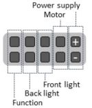
| 1 | 02×05 connector, angled | various | RM2.54mm |
| 3 | reed relay (with diode) | MEDER SIL05-1A72-71D | SIL Form1A |
| 1 | DC/DC converter, 5V 0.5A | RECOM R-785.0-0.5 | SIP3 11.6×8.5mm |
| 1 | WIFI controller | WEMOS D1 mini | — |
| 2 | spacer set for controller | 8-pin | RM2.54mm |
| 1 | motor driver H-bridge, 3.5A | TI DRV8871 | DDA |
| 1 | CMOS Darlington linedriver | ULN2003A | SSOP-16 |
Soldering the PCB board
My best experience is to solder the SMD components first, before soldering the thru holes. I started with the ULN2003A, followed by the resistors and LED’s. Then I mounted the connection pins, relays and sockets for the controller. Then I added the motor driver and resistor on the backside. At last I soldered the DC/DC converter to the board as this is the tallest component.
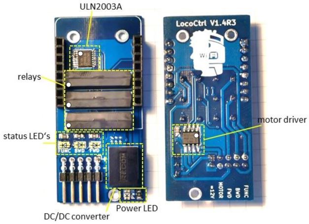
While mounting the motor driver, please make sure, that cooling plate below the chip is properly soldered to the board. Otherwise you will run into a heating issue. Best way is to place just a tiny drop of soldering paste on the cooling plate and solder it with the hot air solder fan. Afterwards you take the ordinary soldering iron and heat it up from the other side through the vias.
As soon as the board is done and the controller is flashed, it just can get plugged onto the board, right over the relays. Keep in mind, that the antenna of the ESP8266 is showing to the upper screwing holes.
Software
Preparation
The freeware Arduino is required for flashing the software to the microcontroller. You just have to connect the WEMOS D1 mini to your computer via USB cable, choose the COM port and do the flashing.
Some knowledge of Arduino is beneficial.
After downloading and installing Arduino, the WEMOS driver needs to be installed. You will a good installation guide (in german) here.
Then install the following add-on packages:
- SPIFFSReadServer by Ryan Downing
- ESP8266WiFi by ESP8266 Community
- ESP8266WiFiMulti by ESP8266 Community
- ESP8266WebServer by ESP8266 Community
- WebSocketsServer by Markus Sattler
- WiFiManager by tzapu, tablatronix
Flashing the controller
Download the sourcecode for the Arduino project plus SPIFFS content in “data” subfolder.
Please make sure to seperate the 4 MByte storage space of WEMOS D1 mini to:
- 1 MByte program code
- 3 MByte SPIFFS
A modification of the source code is not required, because there is no need to change an SSID or WiFi password. This is all handled by the WiFiManager. Compile and upload the arduino source code. Then update the files of the “data” folder to SPIFFS.
As soon as the compiled code and the SPIFFS files are flashed to the microcontroller, you may mount it to the PCB board.
First configuration of WiFi connection
As soon as you supply the board with supply voltage, the controller is acting as WiFi access point (AP). Connect your device to the access point. It is named starting “ESP” followed by the controllers serial number.
To configure the controller open a webbrowser and type the IP 192.168.4.1 into the URL bar. The WiFiManager will guide you to connect to our local WiFi network. The connection parameters (SSID & password) will be the saved locally on your controller. The controller is then not acting as access point anymore. Furthermore it is acting as network client in your local network.
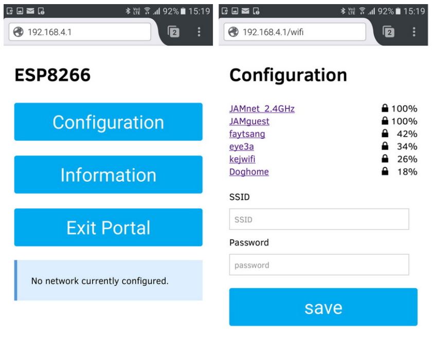
Next time you start the controller in your local WIFI environment, the controller will be connected automatically.
Control your locomotive
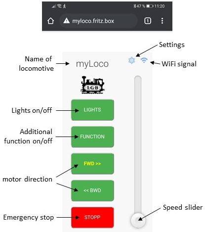
Once the controller is integrated into your local WiFi network, you may call the website by “myLoco” followed by your local domain. As I am having a Fritz!-Box the complete URL is myLoco.fritz.box. The connection will then be established.
Settings
Clicking the gear icon you will get to the settings. In the current version you are able to change and save:
- motor direction – in case you switched the motor cables (only enabled with motor speed = 0)
- front / back lights
- name of locomotive
WiFi signal
This symbol is indicating the WiFi signal strength of the locomotive. It will be updated in short intervals. Three bars is a pretty well connection.
Lights (toggle on/off)
Pressing the “Lights” button, you can switch on/off the front and rear lights. If the button font is yellow and bold, the lights are switched on. The front and rear lights will be automatically switch corresponding to the motor direction.
Additional function (toggle on/off)
With this board you are able to switch an additional function. You may connect a smoke generator of an interior lighting to it. By pressing the “Function” button, you can toggle between on and off.
Motor direction (FWD, BWD)
You may switch the motor direction (and the front and rear lights) between forward (FWD) and backward (BWD) direction. This buttons are disabled as long as the motor is turning. They get enabled again as soon as the motor speed is zero.
Emergency stop
In case of an foreseeable crash or any other issue, it is possible to stop the locomotive immediately by pressing this button. That’s way faster than pulling the speed slider down.
Speed slider
Use the speed slider to change the speed of your locomotive. The higher you pull the slider the faster your locomotive gets. If you want to turn the direction, you have to stop the locomotive, use the FWD/BWD buttons and pull the slider again up to speed. You cannot turn the direction while the locomotive is running.
LocoCtrl Settings
In the settings page, you are able to configure your locomotive. To save and leave the setting page, please click the gear icon.
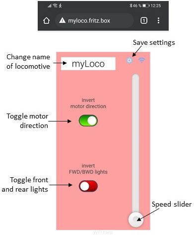
Locomotive name
You may change the name of your locomotive in the way you want. Special characters and spaces are not allowed. So the typing of these characters is prohibited.
Toggle motor direction
In case you mixed up the motor cables by mistake, you are able to toggle the direction by software. This switch is only enabled while the speed is zero.
Toggle front and rear lights
In case you mixed up the wiring of the front and rear lights of your locomotive by mistake, you may toggle it by software using this switch. This setting is independent of the locomotive speed. My advice is to change settings only, while the locomotive is not running.
Conclusion
I guess some background knowledge about electronics, soldering and programming is required for this project. But on the other hand side it has its advantages, such as fun with soldering, changing the scripting in the way you prefer it and so on. It’s cheap, simple and working.
I also installed an additional outdoor WiFi router in my backyard to increase the WiFi signal strength. That’s my advice to establish connections without issues. But that’s all up to you.
I hope you like and enjoy my little project. Let’s see, what’s coming up next… 🙂