Category Archives: Garden Railway

Inspired my Mark Found’s tv series “The Garden Railway”, I started building my own garden railway in my backyard. It is build right from the scretch.

I created this blog in order to share my experiances to interrested people, who also want to start with building up their own garden railway in their own backyard. So every comment and feedback it apreciated.

A garden railway is a great possibility to combine nature and technic in a home environment. It is also a great hobby to free up the mind from daily business. And it is completely different to smaller inhouse scales, because everyone starting with this hobby has also think about weather and stability, security and many other impacts. Working with garden railways needs rockery work, concrete mixing, gardening, and way more.

Please enjoy my little blog. I hope, that I am able to share some good inspirations.

SMOOTH BUT POWERFUL

The ordinary joint controller is build with a usual electric coil and a permanent magnet, that is turing the rails. It really fast, but not really powerful. Just a little piece of gravel is prohibiting its functionality. The resultis really frustrating. So I decided to change this behaviour.

First idea was to use a servo, but the creation of a PWM signal for its control is simply too complicated. So why not usinga simple electric motor with a micro gearbox? Well – that sounds perfect. DC motors are able to spin in both directions. I found a DC motor in an electronic online shop with an integrated 1:1000 gearbox. Next step is to establish an automatic end switch for both directions. I found a great circuit digram in the net. So with some patience I used to original case and replaced to content.

It is working in perfecting. It is moving very smooth, but also very powerful. It is that strong, that it my push 12 kg (24pds)!!! So there shouldn’t be any issue anymore! Let’s turn joints!

CONCRETE WORK

Great weather and time to work. So it is getting time to dosome gardening and set the grass seperator. 4 hours and 240 kg of concrete later I call it the day. After getting some earth out and putting some gravel below als stones are set in concrete.

Next step will be setting the fundamental basement for the tracks. But not today. I feels stoned – need a cold beer.

PREPARATION OF EXTENTION

Prepearation for the last step of track extention for 2017. Goal is to get the tracks in front of the waterfall. So about 5 meters (15 feet) are missing. To keep the grass away from the tracks, a speparation need to be made. First step was to lay down some stones in the way the separation is planed. Second step is to cut off the grass. For getting an idea, how it would look alike, I simply put the tracks temporarly on the earth.

BRIDGE RAILING

After a long period of time, I had the mood to make something new to my garden railway. I build a railring to my bridge. Before summer vacations I already prepared some wood and put some paint on it. Today I screwed it under the tracks. After that I soldered some blank cupper wired to a railing and sprayed it with silver color.

COMPARISION OF SWITCHPOINT LIGHTS

I have three switch points lately in my garden railway – two PIKO R5 switches and one R7 switch. As I want to switch them remote controlled, I also bought the electrical actuator from PIKO, I am very satisfied with, because it is powerful and has rubber deals in order to get it water proof. To get it all complete, I also bought the switch point lights from PIKO. The lights from PIKO look great and convince by a solid plastic construction and LED lights, supporting the load of the power supply.

I installed the complete combination of switch, actuator and light to the final destination, but I realized real quick, that it is not working as expected. So I investigated a bunch of ours to understand, why it is not working. I mechanically disconnected the lights again and it was working again. I strictly observed, that no gravel or dust may block the mechanism and gook everything with oil. The issue seems to be, that the force is transferred over a plastic elbow angle, that seems to cant the mechanism.

After several disappointments I decided to order a light from LGB and tested it. There are several differences between both products. First difference is, that the LGB device it screwed to the actuator by two screws instead of just one, which is increasing the stability. Second difference is, that LGB is using a light bulb instead of a LED. I see this as a disadvantage, because this is putting additional load on the power supply. Third difference is the light cap. PIKO just glued it on top, which is not really a protection – especially if the tracks are outdoors. The light cap of LGB is mechanically pushed and locked. So snow, wind and heavy rain doesn’t have any impact. The forth and most important difference is the mechanical composition. It doesn’t have an angle and is straight forward. So there is no possibility to cant. In some first experiments, the light was blocked as well, but the reason was clarified pretty soon. The pin, that got clipped to the actuator, is moving very close to the lamp socket. I took a sharp cutter knife and smoothen down the edges of the pin. Now it moving in perfection without any issues.

My recommendation is to use switch point lights from LGB in future. They are more expensive and need a higher current, but from a mechanical perspective LGB work way better.
SIGNAL PROTOTYPE DONE

Today I painted and finalized the signal, Thebox, the signal is mounted on, contains the ESP8266 and the power supply unit, coming from the tracks. So it getting very compact and easy to connect.

Would I do something better next time? Of cause! There is always room for improvements. I would take 5mm LED’s instead of 3mm in diameter. I also would take brighter LED’s, because its hard to see the LED’s during daytime. I also would take finished U-profiles made of brass and would not try it on my own.

On the other hand side: its a prototype and I just wanted to see, if it is possible to make this idea become true.

FIRST SIGNAL PROTOTYPE

Today Imade some soldering. I found some cupper plates in my basement and started devoloping the signal by cutting, bending and drilling the parts. As soonas all parts got prepared I started soldering together.

The prototype is not the quality of a mass production, but for the very time it is possible to see, what the idea is.

It will get some painting within the next days. Then the electronics will get included.

SIGNAL CONTROL

Software developed and flashed to the ESP8266-01. I usedto take some CSS elements to display the signal on the website. By clicking on the red circle, the red LED turns red and turns off the green LED. By clicking the green circle – well – guess what happens

I supply the board with 18VAC as I have it at my tracks. The LED’s have a common ground. So just three wired are required to control the LED’s.

OK – result: It took a while, but finally this works.
I “just” need to build the signal out of cupper profiles and mount it on top of the black box with the electronics inside.

ESP8266-01

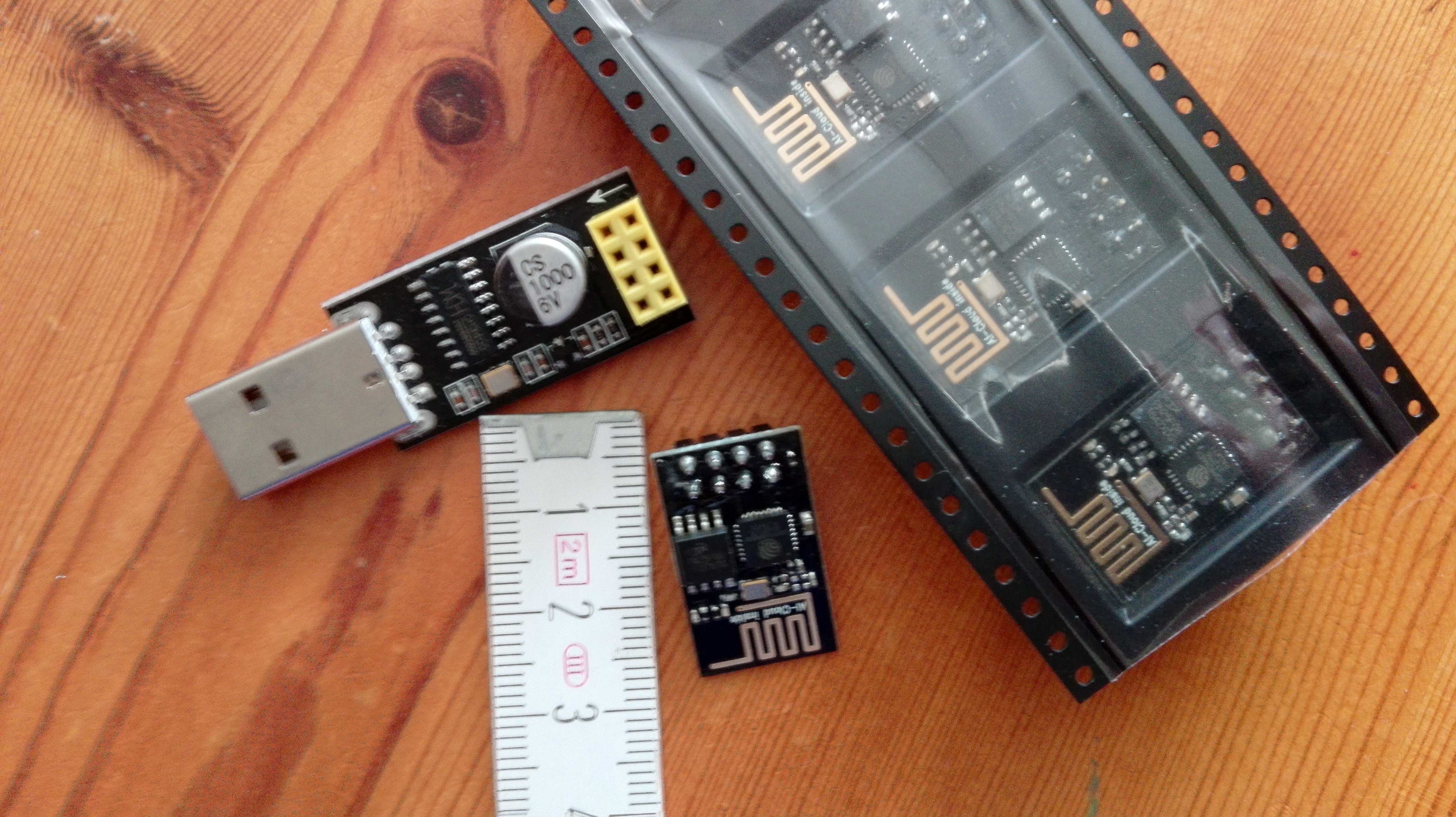
I ordered 5 ESP8266-01 microcontrollers and a programmer kit for controlling my signals. This version of the WIFI controller has 2 GPIO’s, which perfectly fits to control 2 LED’s – a green and a red one.

After digging thru Google, I finally got the Arduino IDE plus ESP8266 plugin. Yesterday I tried some experiments and – tah dah – It is working as webserver…..

Now I’m on to implement a web interface to control the signal. More to come